CoBra - BOOT Software

This page presents a few details about the BOOT software used in the CoBra computer. I'm talking about the code stored in the BOOT ROM, which runs immediately at startup in the startup hardware configuration. Traditionally, back in the day, as a BOOT ROM in CoBra they would use one 2KB EPROM. Nevertheless CoBra can access a BOOT ROM with a capacity of maximum 16KB and, as you will see next, I successfully took advantage of this prerogative.

BOOT ROM images used in CoBra


For each BOOT ROM below, there are 2 links: one for the BOOT ROM code disassembly listing, a click on it will open the listing page, and a link for downloading that binary ROM image

For the 64K RAM configuration

For the 80K RAM configuration

Standard BOOT (v.1)

ROM Image (Right-click, Save As)
This is the version I recovered from an EPROM I kept since the old days (1990-1992). I used it initially, when I brought up the first mainboard in the 64K RAM configuration. The code is identical with the "boot64k_v2.bin" file in the "Cobra_BOOT_roms.zip" archive posted on the forum by mihaila_ac. Standard BOOT (v.1)

ROM Image (Right-click, Save As)
This is the version I recovered from the EPROM on the mainboards I built back then (1990-1992). I used it on both those mainboards after modifying them for 80K RAM. This version is almost identical to the one in the "boot80k_v3.bin" file in the "Cobra_BOOT_roms.zip" archive posted on the forum by mihaila_ac.
Standard test BOOT

ROM Image (Right-click, Save As)
The standard test BOOT code for CoBra. It was initially written for the 64K RAM configuration. I modified it so that it can be run in both configurations (64K and 80K).
HOMOK Test BOOT

ROM Image (Right-click, Save As)
A BOOT code received from a friend, with hardware tests for CoBra in 64K RAM configuration BOOT "Mastery Electronics"

ROM Image (Right-click, Save As)
A BOOT code received from a friend, essentially the same as the standard BOOT 80K code but with different graphics

CoBra Boot Manager

Aside from these BOOT code versions, I personally wrote a code I named "Boot Manager", which is run instead of the usual BOOT code, from address 0000h. At startup a menu is displayed where one of the BOOT codes presented in the table above can be selected. My idea was to somehow make it possible at startup to choose one of these BOOT codes to execute, without having to pull out and replace the ROM chip on the mainboard. The purpose is rather historical, I wanted to somehow be able to preserve these different BOOT codes, written by various people for CoBra, as in some BOOT code museum, if I can say so.

The assembler source code is shown below, and can be downloaded, as well as the assembled binary code (MasterBoot-CoBra+CPM_rev.01.bin) with a right-click on the two links in the table header.

CoBra Boot Manager - Assembler source

(MasterBoot-CoBra+CPM_rev.01.asm) (MasterBoot-CoBra+CPM_rev.01.bin)

The BOOT code created this way, which I named "Unified CoBra Boot", fits the max. 16 KB of the BOOT code area which CoBra can address at startup.

It contains the 2KB Boot Manager at 0000h, and right after that, the BOOT codes listed in the table above, but modified by me so they can run relocated to an address different than 0000h.

The memory areas occupied by these components of the "Unified CoBra Boot" - the way I chose to place them, is as follows: (the assembled binary code for the entire 16KB BOOT ROM can be downloaded with a right-click on the link on the right)

Memory map for the "Unified CoBra Boot"

Free space$3000-$3FFF The file 16K_UNIFIED_BOOT_rev.01.bin you can download here ($3000 = 12288 bytes, since $1000 bytes are left unprogrammed) contain the image of a 16KB BOOT ROM for CoBra, which you can write to an EPROM and use in a CoBra computer, regardless of whether it has a 64KB or 80KB hardware configuration. I suggest using it in conjunction with the 64KB SYSTEM ROM image downloadable below, which also contains a CP/M system bootable directly from ROM (only in 80KB hardware configuration), using one of 4 possible key combinations (see the keys described below).
"Mastery Electronics" 80K RAM BOOT$2800-$2FFF
Standard 64K / 80K RAM test BOOT$2000-$27FF
HOMOK 64K RAM test BOOT$1800-$1FFF
Standard (v.1) 80K RAM BOOT$1000-$17FF
Standard (v.1) 64K RAM BOOT$0800-$0FFF
CoBra Boot Manager$0000-$07FF

Memory map for the SYSTEM ROM usable with the "Unified CoBra Boot"

Free space$F34B-$FFFF The file SYSTEM_ROM.bin which you can download here ($F34B = 62283 bytes, since $0CB5 = 3253 bytes are left unprogrammed) contains the image of a 64KB SYSTEM ROM for CoBra, which you can write into an EPROM and use in a CoBra computer, in conjuction with the 16KB "Unified CoBra Boot" image above, containing code for launching the CP/M system stored in this SYSTEM ROM (only in the 80KB hardware configuration), using one of 4 possible key combinations (see the keys described below).

NMI routine$F20E-$F34A
15 unused bytes ($00)$F200-$F20E
80-text-columns CP/M$C000-$F1FF
DEVIL$8000-$BFFF
BASIC Spectrum$4000-$7FFF
OPUS v.3.2$0000h-$3FFF

IMPORTANT!:

  • Launching the CP/M system stored in the SYSTEM ROM presented above REQUIRES using the "Unified CoBra Boot" presented above,
  • Launching the CP/M system stored on FLOPPY DISK is done by first launching (from the "Unified CoBra Boot" start menu) one of the old BOOT ROM codes, and then from this old BOOT code, using the D key, a CP/M system can be loaded from the floppy disk.

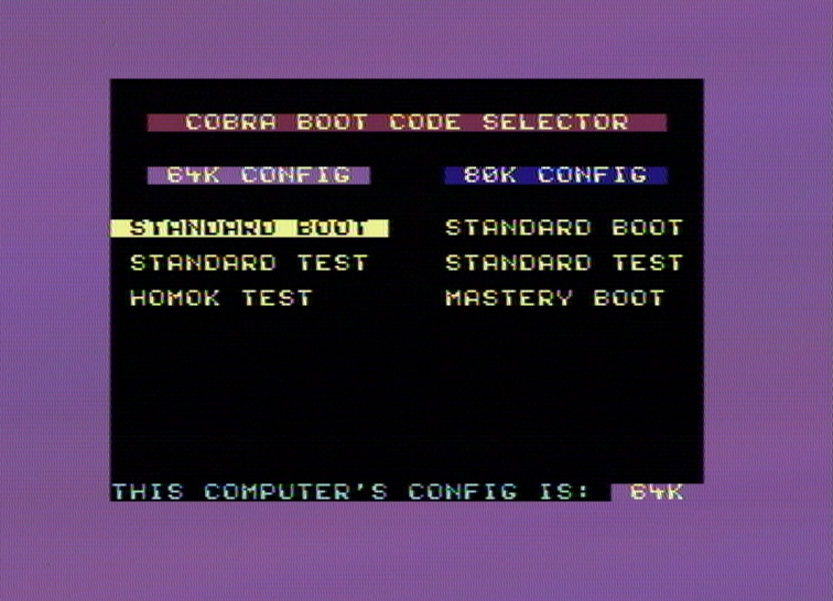
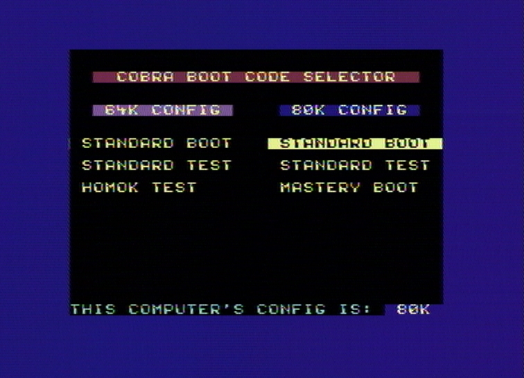
At computer startup, the screen will show one of the two menus below, depending on your hardware configuration:
For 64K CoBra the menu on the left will be displayed, and for 80K CoBra the menu on the right.

Boot Manager on 64K RAM CoBra

Boot Manager on 80K RAM CoBra

Startup menu displayed by the Boot Manager for the 64K RAM configuration.

With the UP/DOWN arrow keys you can select one of the 3 BOOT codes available in the menu on the left, then with ENTER that code can be run.
Startup menu displayed by the Boot Manager for the 80K RAM configuration.

With the UP/DOWN arrow keys you can select one of the 3 BOOT codes available in the menu on the right, then with ENTER that code can be run.

That means this code autodetects the computer hardware configuration. The active menu of which you can choose one of the actual BOOT codes will be determined depending on the configuration: for 64K CoBra the menu on the left will be active and for 80K CoBra the one on the right.

Also the following key (combination)s are active: NOTE:

1. When loading CP/M from ROM, the system will need a floppy disk to be present in the default drive you choose. The disk does neither need to be bootable (system disk) nor to contain any file, but it must be at least formatted. You can very well use a hardware floppy emulator, with a CoBra CP/M 720K floppy image, which would emulate a physical drive connected as drive 0, 1, 2 or 3 (the system code selected by CTRL+n described above).

2. Key "4" listed above will not work correctly with the SYSTEM_ROM.bin image posted here, because this image contains in the upper quarter (C000-FFFF) the CP/M image loadable from ROM, which of course must be started in CP/M hardware configuration, not in BASIC configuration. When I wrote the Boot Manager, I did so for the general case of a 64KB SYSTEM ROM containing 4 BASIC-type operating systems, 16KB each. Later on I came up with the ROM-loadable CP/M "trick", which I put in the upper quarter of SYSTEM ROM instead of a BASIC with NMI.

3. Key "N" - for loading the NMI Basic - will load in the RAM memory the standard BASIC which also loads when pressing "B", in which then will be inserted a piece of code written by me for a NMI routine. Details about using this routine are given in the "Software" -> "BASIC + NMI" section.

CoBra Boot Manager - anniversary version 2016

In 2016, being the 30th anniversary of the design and construction of the CoBra computer, I came up with the idea of adding an "animation with a dedication" to the Boot Manager, for the entire team who designed and built the computer back in 1986. So I got to work and I wrote a modified version of CoBra Boot Manager containing a vertical (upward) scroll of the CoBra logo, which moves into the upper third of the screen, after which, in its old place in the middle third, also by vertical scroll upwards is introduced the "30 ANI" logo ("30 YEARS"). Then in the lower third of the screen an anniversary message is displayed, after which all the names of the CoBra designer team members are introduced one by one. Next, the "30 ANI" logo starts a classic horizontal scroll, right-to-left, alternating with the left-to-right scroll (in the background) of a slanted banner with multicolored stars. I'm showing below the Assembler code for this version, which can be downloaded together with the binary code produced by assembly (MasterBoot-CoBra+CPM_rev.02_Anniversary_Edition.bin) with a right-click on each of the two links in the table header.

CoBra Boot Manager - 30-year anniversary version - Assembler source


(MasterBoot-CoBra+CPM_rev.02_Anniversary_Edition.asm) (MasterBoot-CoBra+CPM_rev.02_Anniversary_Edition.bin)

Difficulties in writing the CoBra Boot Manager

When writing the Boot Manager I had to deal with two problems:
  1. Writing code which would work as BOOT machine code for CoBra
  2. Modifying the original BOOT machine codes listed in the table so they can run relocated to addresses other than 0000 where they normally run from

1. Writing code which would work as BOOT machine code for CoBra


    1. The main problem when writing BOOT code for this computer is the way the 8255 circuit exits the RESET state. I'm talking about the fact that the RESET input of 8255 is activated on a logical level of "1", while the Z80 CPU generates a RESET signal active on a logical level of "0". For better unserstanding, we need to examine the Configurator and selector circuit. As the hardware manual says, diode D02 makes sure the CPU exits the RESET state a few miliseconds before the NPOR signal is deactivated (it is active on a "0" level). The NRST signal used for Z80 is created on the anode of D02, while NPOR is created on its cathode. And the NPOR signal, after passing through the inverter gate U17/8,9,10, becomes the POR signal which is taken to the RST input of 8255. So basically Z80 exits the RESET state quite earlier than 8255. And this can cause problems at startup because 8255 generates a few signals which are used to determine the hardware configuration of the computer, more precisely O5 and especially O6, therefore creating the need for a routine at the beginning of the BOOT code which would provide a certain delay before attempting to configure the 8255 interface. 8255 can operate in many configurations, but in CoBra it is only used in one: ports A and B as input ports, and port C as output port. Its configuration is accomplished by a sequence of OUT instructions executed by the Z80 CPU, and these must be executed with a little delay after the computer startup, in order to give 8255 enough time to exit its RESET state, otherwise the OUT instructions will have no effect.

    2. Another aspect of writing a BOOT code pertains to programs (usually games, but not only) designed to run under Spectrum BASIC, stored on CP/M floppy disks and run from CP/M. At first sight, these two things may not seem to have any connection, but...

What happens when running such a program? A CP/M executable file (.COM), is run, containing the code of the actual program preceded by a short piece of code they would usually call back then "Loader". Since the Loader code is at the very beginning of the executable file, it will be executed first when the .COM file is run. What should happen is the Loader should load the code of the Spectrum program into memory at the proper address, change the computer hardware configuration from CP/M to BASIC configuration, and then hand control over to the Spectrum program. In order to understand the problem, I will list below the disassembly of the Loader code extracted from the first sector of a Spectrum game ("Matchday") - randomly selected out of those kept on my CP/M floppies - along with some comments:

"CPM Game Loader.asm" is a short piece of code, taking up a little space at the beginning of a sector (1 sector = 512 bytes, most of which is in this case unused, full of $00 bytes) which launches a Spectrum application from CP/M. It is attached to the beginning of the actual application and the result is saved to disk as CP/M executable (.COM).
**********************
This Loader is designed to work in conjunction with the standard CoBra 80K BOOT code (more exactly with the BASIC loader routine at 0038h in the CoBra 80K BOOT code). In other words, if you intend to write a new or different CoBra 80K BOOT code, YOU NEED TO HAVE THIS ROUTINE PRESENT AT 0038h.
**********************
The Loader loads the application code into the standard Spectrum memory area (4000-FFFF, that is DRAM#1-#3), then it switches the computer to BASIC hardware configuration, it loads BASIC from ROM and it launches the application from its entry point.

In order to go from CP/M configuration (PO=0, LO6=1) to Spectrum configuration (BASIC, PO=0, LO6=0), the computer must first go through the startup configuration (COBRA, PO=1, LO6=1). The explanation for this fact can be found analyzing the Configurator and selector circuit in the CoBra schematics. In essence PO is the output of a flip-flop (half of 7474) and PO drives the clock input of a second flip-flop, whose output is LO6. Since 7474 has clock inputs active on the rising edge, this means that if PO="0", (PO="1"), and in order for the second flip-flop's state to change, PO must go to "1" and then back to "0".

The Loader code switches the computer to startup configuration and ends with an RST 38h instruction. That means a jump to 0038h in startup configuration, which is located at the beginning of the BOOT ROM.

At 0038h, the CoBra 80K BOOT code contains a routine which loads an operating system from ROM (BASIC, OPUS, DEVIL etc.) into DRAM#0 and then changes the hardware configuration to Spectrum configuration, after which it jumps to the address stored in the HL' register. That's exactly what the CP/M game loader stores in HL' before exiting CP/M: the start address of the Spectrum application. Obviously that instruction (line 0024h, LD HL,$4600) must be modified depending on the specific Spectrum application in order to contain its correct start address.

If the SYSTEM ROM size is greater than the standard 16KB, the operating system being loaded is selected by the SO signal (Serial Out) from 8255/pin 10, which is traditionally connected to the A14 address line of SYSTEM ROM.

The de facto standard, back then, was to store Spectrum Basic in the 4000-7FFF range of a 32KB ROM (that is, the upper half), therefore the SO signal must go to "1" in order to load Spectrum Basic.

2. Modifying the original BOOT machine codes


In order to modify the original BOOT codes listed in the previous table I had to first disassemble each code and analyze all of it. Then I marked all lines containing absolute jumps (JP), subroutine calls (CALL) and register load instructions manipulating values later on used as addresses located within the BOOT code. Then I made a list of all locations that had to be modified and I manually modified these locations within that particular original BOOT code. A click on the name of any BOOT code in the previous table will show its disassembly, along with my comments and these lines marked at the end with the string "---@@@".