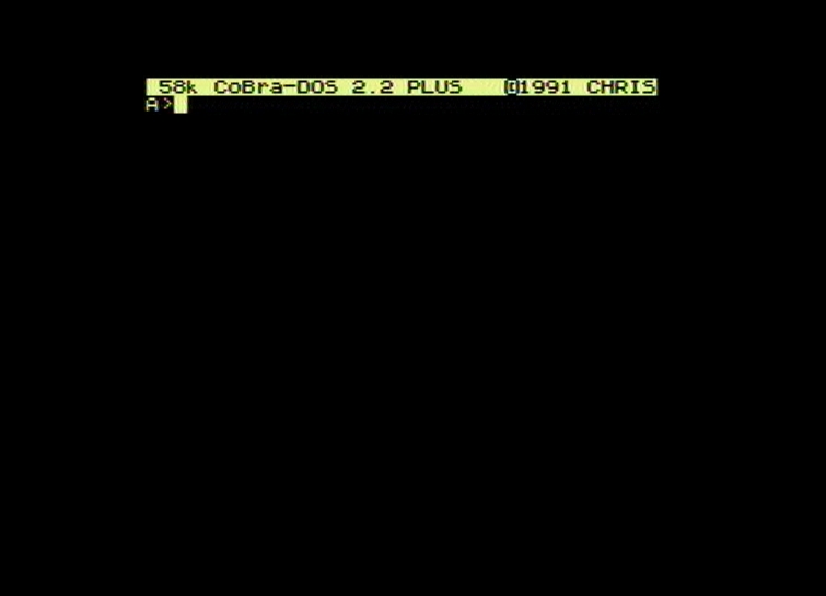
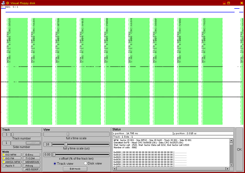
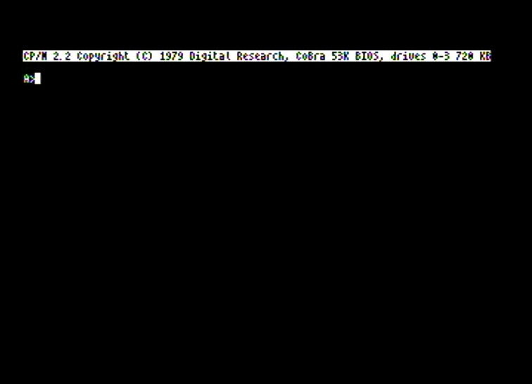
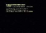
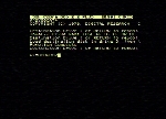
CoBra - CP/M Operating System with 80 text columns visible

1. Installation procedure


The first time this operating system got to me, it was in two versions, each one as two CP/M files: Both install procedures above generate a "virused" operating system, which will assail and irreversibly mess up the disk directory in case of any error like BAD SECTOR, READ ID DENSITY etc., unless of course the floppy disk is WRITE PROTECT! Aside from that, after this feat, the system resident in memory will irreversibly go fishing, so that it will have to be reloaded from another disk. All this because the system generator had been probably copied originally from a copy-protected disk, the result being an "infested" copy.

The great trick that makes this operating system very interesting is that it displays 80 text columns on screen (visible at once), using a little hardware modification in the CoBra schematics, a modification whose schematic was given to me at the same time with the two executable files. The original modification contained only a few diodes and had to be manually activated, using a switch to change between the configuration in the original schematics and the new configuration, modified to allow displaying an extended screen (wider than the SCREEN area of a standard Spectrum 48). Two roommates I had back then (Traian Onciu and Dan Teodorescu) - according to what Traian says he remembers today - procedeed to make a little modification in the SY80CHR.COM executable, and then redesigned the schematic of the modification, replacing the diodes and the switch with TTL gates and a multiplexer. The result was that the system no longer required manual switching between the standard configuration and the extended display config, this being done automatically at system boot time. But the bigger problem still remained, the system was still unsafe to use because it would delete the system disk anytime its demons would haunt it.

Since I did not like this, I tried and succeeded to study (by disassembling) the code in the SY80CHR.COM executable "improved" by my roommates and to modify it in order to eliminate the "trap". Thus I obtained a system generator completely "disinfected" as well as "automated". I saved the executable "unprotected" this way under the name SY80CAT+.COM.

As a consequence, installing of this CP/M operating system can be done by running the SY80CAT+.COM executable, followed either by copying the CBOT.SYS file onto the new system disk, or by running the MDC80CHR.COM executable which would copy the basic utilities onto the new system disk.

Important to note: in order to run a CP/M executable error-free, the size of it must be less than the maximum size of the TPA area allowed by the system. For the CP/M version I use here to run SY80CAT+.COM (22 KB) and MDC80CHR.COM (42 KB) the max TPA size is 58 KB, so there will not be any problems.

Next I will describe the installation procedure for this CP/M version using the executables SY80CAT+.COM and MDC80CHR.COM (MDC80CHR.COM is not "infected" in any way, doesn't pose any problems, it does nothing but copy the basic utilities to disk, making sure D.COM will have the CP/M Loader code at its end, in the required location on disk).

1:

I loaded the CHRIS INSTALL version of CP/M with 40/64 text column display.

2:

Next I typed the command to run the system generator which writes the system code in tracks 0 and 1 of the disk.

3:

After an ENTER, a message is displayed requesting specification of the target drive.
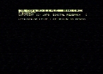
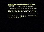
4:

Deoarece mesajul iese din fereastra vizibilă de 40 de coloane text, pagina video se schimbă automat, afișîndu-se jumătatea din dreapta a ecranului virtual de 80 de coloane cu restul mesajului.
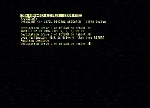
5:

Pentru a obține o afișare mai coerentă, am apăsat tasta GRAPH NORM, care schimbă numărul de coloane text vizibile din 40 în 64, reușind să încadrez tot mesajul în porțiunea vizibilă a ecranului text virtual.
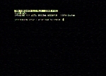
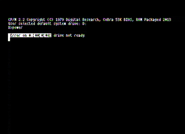
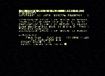
6:

În continuare am încercat să specific unitatea destinație prin codul numeric al unității fizice. Vreau să instalez sistemul pe discul prezent în unitatea 3. Dar programul protestează că vrea să i se precizeze codul unității logice (A:, B:, C: sau D:)
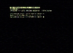
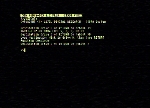
7:

Așa că apăs și eu tasta D, întrucît unitatea fizică 3 corespunde unității logice D:. După care programul cere apăsarea tastei ENTER, după ce discheta destinație este introdusă în unitatea D:.
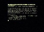
8:

După copierea sistemului în pistele sistem, se așteaptă repetarea operației prin precizarea din nou a unității destinație, sau terminarea prin apăsarea tastei ENTER.

9:

Apăs ENTER și ies din program.

10:

Apoi tastez numele executabilului care instalează utilitarele de bază cu tot cu CP/M Loader.
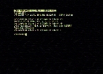
11:

Și apăs din nou tasta GRAPH NORM pentru a obține o afișare mai clară.

12:

După un ENTER apare un mesaj de start și programul cere din nou precizarea unității destinație.

13:

Conform lecției învățate, apăs tasta D, și apoi programul cere introducerea dischetei în unitatea D după care așteaptă confirmarea cu un ENTER.

14:

După terminarea copierii, programul întreabă dacă se dorește repetarea operației.

15:

Apăs N și ies din program înapoi la promptul CP/M.


2. Operating system description


This system (in its original form) is ONLY bootable from physical drives 2 and 3. More precisely, if double density drives are used, they can only be used with this operating system as physical drives 2 and/or 3. Physical drives 0 and 1 are assumed to be single density, with a different number of sectors/track. The code in BOOT ROM knows how to load the CP/M system from any physical drive (0-3), but CP/M itself, once loaded, will not be able to access the disk it was loaded from unless that physical drive has the proper density (drives 0, 1 SD, drives 2, 3 DD).

CP/M loading is done from the standard CoBra BOOT under the 80 KB RAM hardware configuration, by pressing the D key.

The startup sequence of the system, the way it is displayed on screen when pressing the D key in the boot configuration, looks like this:
(hover the mouse cursor over the left column, from top to bottom, and watch the big image on the right)

1:

2:

3:

4:

5:


For a thorough understanding of how the extended display works, hardwarewise, please read the paragraph describing this modification, on the functional comments page in the mainboard section. Basically, under this O.S. the standard Spectrum SCREEN area is extended to the left and right by 4 standard Spectrum characters. That means an extra 4 x 8 = 32 pixel area horizontally, to the left and right, to the detriment of the BORDER area. This way, the usable display resolution becomes 256 + 32 + 32 = 320 pixels horizontally and the same standard 192 pixels vertically as in a standard Spectrum 48. So 320 x 192 pixels. And this, combined with the usage of 4 x 8 pixel narrow format characters, allows a text screen with the dimensions of 320 / 4 = 80 caracters per line and 192 / 8 = 24 lines, that is a text screen having 80 x 24 characters displayable at once. For a practical illustration, I will show next a snapshot generated after running the CU.COM (CoBra Utilities) utility, by which I modified the BORDER color as well as the INK and PAPER colors, for a thorough representation of the display capabilities:


Note the much narrower BORDER area to the left and right, compared to the standard Spectrum display mode in the image below:


An interesting detail: the characters displayed in the extended area are stored in the upper half of the video memory, whose size is 16 KB. But since we're only talking about a 4 Spectrum character wide area on each side of the standard a Spectrum SCREEN, this half of video memory is only partially used. Data being displayed takes up 8-byte segments which are separated by 24-byte free memory segments. In these free memory segments, the operating system is designed such that it stores a full copy of the CCP module, and when exiting a transient CP/M program, instead of needing a disk access for bringing CCP back in the system memory, it brings it back directly from the video memory. This way the disk is less accessed, reducing floppy disk wear. Congratulations to Marcel Arefta for this superb CP/M trick !

The BIOS is written such that it expects the physical drive numbers 0 and 1 to be 8" SSSD drives (26 sectors/track, having 128 bytes/sector) and the physical drive numbers 2 and 3 to be 5.25" (or 3.5") DSDD 720K drives. Since 8" drives are basically non-existent nowadays, that means the only physical drive numbers usable with this O.S. are 2 and 3.

Aside from this, this O.S. is designed such that if the system is loaded from drive 2, this becomes logical drive A: (instead of C:, which would be the normal behavior) and the letter C: is assigned to the physical drive 0.

That means, although the BOOT code can load CP/M system from any drive (0, 1, 2 or 3), if only 5.25 or 3.5" 720K drives are used, system will only be loadable from drives 2 or 3. Further more, neither after the system is loaded drives 0 and 1 will be usable, since the O.S. expects them to be Single Density 8" drives.

For this reason, presently I decided to modify the operating system code, as described next, aiming for three goals:

3. Identification and disassembly of system components: CCP, BDOS, BIOS


The starting point in the analysis of the CP/M operating system is the system loading routine in the BOOT ROM which fetches the code from the disk system tracks into the computer's DRAM memory. By analyzing this routine I found out how the system loads from disk from scratch.

The loading process for this version of CP/M has the following steps:
  1. When pressing the D key in the BOOT hardware config, the CP/M loading routine in BOOT ROM searches and locates a hidden sector on disk containing a piece of code called "CP/M Loader". It loads it in memory starting from address $FC00 and it executes it. Ca să intru în detalii, algoritmul de localizare a CP/M Loader-ului pe disc este următorul: (se poate afla prin studierea codului dezasamblat de BOOT ROM 80K)

    1. The first 64 records in the disk directory are read into memory, that is the first 2KB of the directory;
    2. Within these records, a search is then started for the first filename having user number 0 and a "SYS" extension, where the 3 bytes of the extension can have bit 7 set or not ($53, $59, $53 or $D3, $D9, $D3). On the floppy images in my archive this file is named CHRIS.SYS sau Kryss.SYS, where the extension bytes have bit 7 set, which means the extension is non-printable;
    3. If the file is found, the address of its first allocated block on disk is read, let us name it B. Both previously mentioned files, CHRIS.SYS and Kryss.SYS, have in their associated directory record only one block address, which is $0007, therefore B=7;
    4. An absolute sector address is being computed as Sect# = (B * 8) + 1 = 57;
    5. The number of sectors per track being used is 36;
    6. A track number is being computed as Trk# = Sect# DIV 36 + 2 = 3 (where DIV is the integer division operator);
    7. A sector number (within a track) is being computed as Sec# = (Sect# MOD 36 - 1) DIV 4 + 1 = 6;
    8. This sector number is being translated using a translation table (1 5 9 4 8 3 7 2 6) yielding as result Sec# = 3;
    9. Starting at memory address $0000 the following sectors are being read from disk into memory: Sec# from track number Trk# side 0 and Sec#+1 from track number Trk#+1 side 0;
    10. A jump is executed to address $0000 starting the execution of the code stored in the sectors read, which are expected to contain the CP/M Loader code.

    If we study the disk allocation, we find that sector 3 on track 3 side 0 is the last sector of the last block (block $0004) allocated to the D.COM file, and the data area of this file ends before the last 3 sectors of its last block. Block $0004 contains sectors 6, 8 from track 2 side 1 and sectors 1, 3 from track 3 side 0, and the contents of the D.COM file ends with sector 6 from track 2 side 1. For this reason it can be said that sector 3 from track 3 side 0 is a "hidden" sector, since it is "officially" allocated to the D.COM file, but it actually contains something else than the data bytes of this file.

    This whole algorithm is nothing but a big dumb contraption, since the block size used in calculation (1KB) is wrong (the block size used on DD floppies is 2KB) and also the number of sectors per track used (36) is also wrong (DD floppies have 9 sectors per one track side). In order to make the contraption work, 7 was chosen as number of allocated block for the Kryss.SYS file which actually has zero length and only exists as a directory entry, so that the result of the algorithm can be sector 3 track 3 side 0, which is exactly the area where the generator of this CP/M system has written the last block of the D.COM file when the system was installed on disk. If the D.COM file (also obviously rigged so this entire moronism would work) were replaced with its original version as written by Digital Research, the CP/M system would not load from disk. Obviously, the purpose of this whole masquerade is to hide by any possible means the CP/M Loader code from "uninitiated" users.

    The interesting thing is that originally, the CoBra CP/M system had been designed to work with the CP/M Loader saved to disk as an independent, completely non-obfuscated file, which could easily be copied and studied by anyone. The file was named LK.SYS and in order to work it had to be the very first file saved to the system disk, meaning it had to be saved to block number 2, which is the very first data block available for file allocation. If we use 2 as block number in the algorithm described above, we get Trk# = 2 and Sec# = 8. And sector 8 from track 2 side 0 is exactly the very first data sector available for file allocation on disk, therefore the algorithm also works correctly for a CP/M Loader saved to disk as a regular file in the first allocable sector.

    In fact, the first installation procedure of this CP/M system (described at the beginning of this page, using the AMTISYS.COM and CBOT.SYS files) does exactly that, since the CBOT.SYS file contains exactly the CP/M Loader for this version of CP/M system, as a standard copyable file.

  2. The "CP/M Loader" then loads all sectors of the disk system tracks (tracks 0 and 1) into memory, in their physical order (track 0 side 0, track 0 side 1, track 1 side 0, track 1 side 1). They are loaded in memory starting from address $0000. After all sectors have been loaded, a jump is made to address $0000, meaning the code in the first sector on disk is executed (track 0 side 0 sector 1). This is called "Boot Sector".
  3. The "Boot Sector" code relocates the system components (CCP, BDOS, BIOS) to the locations where they normally run from and then makes a jump to the WBOOT routine within BIOS, this way effectively bootstrapping the system.

CP/M Loader - disassembled code

Boot Sector - disassembled code


At the time when I started this project, I had at my disposal an archive of all the 3.5" floppies used by me with CoBra back in the day, which flopies, around '95-'97, I had the inspired idea to backup using Teledisk and store the generated floppy images on a data CD. These 3.5" floppies were left behind in my country when I left, but I did take with me all the physical 5.25" floppies used with CoBra. Therefore I started this project with the Teledisk images of the 3.5" floppies and the physical 5.25" floppies.

Five of the 3.5" floppies contained CP/M utilities, which I had made system bootable disks back in the day, using this 80 chars/line CP/M system. So I took the SAMdisk utility (by Simon Owen) and using it I made a hex text dump of the system tracks (0 and 1, both sides) in the floppy images UTILS1.TD0, UTILS2.TD0, UTILS3.TD0, UTILS4.TD0, UTILS5.TD0, by running the following commands (in Linux, in bash):

> wine SAMdisk.exe view UTILS1.TD0 -c0 > UTILS1_systrk_hexdump.txt
> wine SAMdisk.exe view UTILS1.TD0 -c1 >> UTILS1_systrk_hexdump.txt
> wine SAMdisk.exe view UTILS2.TD0 -c0 > UTILS2_systrk_hexdump.txt
> wine SAMdisk.exe view UTILS2.TD0 -c1 >> UTILS2_systrk_hexdump.txt
> wine SAMdisk.exe view UTILS3.TD0 -c0 > UTILS3_systrk_hexdump.txt
> wine SAMdisk.exe view UTILS3.TD0 -c1 >> UTILS3_systrk_hexdump.txt
> wine SAMdisk.exe view UTILS4.TD0 -c0 > UTILS4_systrk_hexdump.txt
> wine SAMdisk.exe view UTILS4.TD0 -c1 >> UTILS4_systrk_hexdump.txt
> wine SAMdisk.exe view UTILS5.TD0 -c0 > UTILS5_systrk_hexdump.txt
> wine SAMdisk.exe view UTILS5.TD0 -c1 >> UTILS5_systrk_hexdump.txt

I used this command sequence in order to generate a listing of each track which would contain a continuously ordered representation of the data in the system tracks, that is - for each track - first the sectors on side 0 and then those on side 1. By default SAMdisk lists all tracks on side 0, after which it proceeds with side 1, which doesn't exactly fit the bill here.

Then I replaced the text "UTILSn" (n=2,3,4,5) in the "UTILSn_systrk_hexdump.txt" files, with "UTILS1", in order to be able to make a checksumed comparison with MD5SUM of all the 5 files (aside from the "UTILSn" string, in theory there should be no other differences between these 5 files).

As a result of the command "md5sum *systrk*", I got the following checksums:

845e8f608cd9c609cc5ad8164c5a203a  UTILS1_systrk_hexdump.txt
6d46d60edf4e075ce11d67faa4e1d664  UTILS2_systrk_hexdump.txt
845e8f608cd9c609cc5ad8164c5a203a  UTILS3_systrk_hexdump.txt
845e8f608cd9c609cc5ad8164c5a203a  UTILS4_systrk_hexdump.txt
845e8f608cd9c609cc5ad8164c5a203a  UTILS5_systrk_hexdump.txt

As seen above, the checksums are identical for UTILS1.TD0, UTILS3.TD0, UTILS4.TD0 si UTILS5.TD0. Most likely the UTILS2 disk had some writing errors, because its structure, as listed by SAMdisk, looks like this:

> wine SAMdisk.exe scan UTILS2.TD0
[UTILS2.TD0]
80 Cyls, 2 Heads:
250Kbps MFM, 6 sectors, 512 bytes/sector:
  0.0  1[r] 1[r] 6 7 8 9
250Kbps MFM, 9 sectors, 512 bytes/sector:
  1.0  1 2 3 4 5 6 7 8 9
  2.0  1 2 3 4 5 6 7 8 9
  3.0  1 2 3 4 5 6 7 8 9
	.
	.
	.
 79.0  1 2 3 4 5 6 7 8 9
250Kbps MFM, 9 sectors, 512 bytes/sector:
  0.1  1 2 3 4 5 6 7 8 9
  1.1  1 2 3 4 5 6 7 8 9
  2.1  1 2 3 4 5 6 7 8 9
  3.1  1 2 3 4 5 6 7 8 9
	.
	.
	.
 79.1  1 2 3 4 5 6 7 8 9

that is, it's clearly visible that track 0 side 1 only has 8 sectors (instead of 9) of which the first 4 have the same number, 1, which is an error, most likely from the formatting process. Besides, in the present I noticed that actually the UTILS2 disk is not even bootable, which was to be expected.

Next, I will make reference to 2 files:
  1. The hex image of the system tracks generated in the "UTILS1_systrk_hexdump.txt" file (that is the correct, error free, image of the system tracks).
  2. The CP/M memory hexdump from $0100 to $FFFF, generated in the "snapshot 0100-FFFF.bin" file. I saved this image using the built-in SAVE command in CP/M (SAVE 255,MEMDUMP.BIN, then I transferred the MEMDUMP.BIN file to the Linux filesystem and renamed it to "snapshot 0100-FFFF.bin"). Note that, since the SAVE command can only save system memory from address $0100, the addresses listed at the beginning of each line must be added to $100 in order to show the actual memory address.
Below I show the contents of these 2 files, beside each other, for a comparison. By comparing these files, we can identify and precisely locate the CP/M components within the system tracks data extracted from floppy disks.

UTILS1_systrk_hexdump.txt

snapshot 0100-FFFF.hexdump


For a proper analysis we also need a dump of the CP/M system memory area between $0000-$00FF under this operating system. Since the SAVE command cannot save this part of memory, I did it with the POWER.COM utility executed in CP/M right after loading the system. Using the „DUMPH 0, 100” command I got the following listing:

0000: C3 03 DF 80  00 C3 06 D1  00 00 00 00  00 00 00 00
0010: 00 00 00 00  00 00 00 00  00 00 00 00  00 00 00 00
0020: 00 00 00 00  00 00 00 00  00 00 00 00  00 00 00 00
0030: 00 00 00 00  00 00 00 00  00 00 00 00  00 00 00 00
0040: 00 00 00 00  00 00 00 00  00 00 00 00  00 00 00 00
0050: 00 00 00 00  00 00 00 00  00 00 00 00  01 3F 3F 3F
0060: 3F 3F 3F 3F  3F 3F 3F 3F  00 00 00 74  00 20 20 20
0070: 20 20 20 20  20 20 20 20  00 00 00 00  00 00 00 00
0080: E5 E5 E5 E5  E5 E5 E5 E5  E5 E5 E5 E5  E5 E5 E5 E5
0090: E5 E5 E5 E5  E5 E5 E5 E5  E5 E5 E5 E5  E5 E5 E5 E5
00A0: E5 E5 E5 E5  E5 E5 E5 E5  E5 E5 E5 E5  E5 E5 E5 E5
00B0: E5 E5 E5 E5  E5 E5 E5 E5  E5 E5 E5 E5  E5 E5 E5 E5
00C0: E5 E5 E5 E5  E5 E5 E5 E5  E5 E5 E5 E5  E5 E5 E5 E5
00D0: E5 E5 E5 E5  E5 E5 E5 E5  E5 E5 E5 E5  E5 E5 E5 E5
00E0: E5 E5 E5 E5  E5 E5 E5 E5  E5 E5 E5 E5  E5 E5 E5 E5
00F0: E5 E5 E5 E5  E5 E5 E5 E5  E5 E5 E5 E5  E5 E5 E5 E5

As we (should) know, the address in memory locations $0001 and $0002, minus 3, represents the starting address of the BIOS module for any system implementation. From the listing above we can see this starting address in our case is $DF00.

Also as we (should) know, the address in memory locations $0006 and $0007 is used as the end of the TPA memory area. That would be the beginning of BDOS. So the beginning of BDOS would be at $D106.

1. BIOS
********
In "UTILSn_systrk_hexdump.txt", by comparison with the byte sequence in "snapshot 0100-FFFF.bin" starting at $DE00 (which is $DF00 in the actual system memory), we can see that BIOS is located on cyl00/side1 in sectors 4 5 6 7 8 9. Aside from this actual code area (which I named BIOS-1), next the BIOS also includes the area between cyl01/side0/sec1 - cyl01/side1/ 1/2 sec1, which is a system scratchpad area.

2. BDOS
********
Furthermore, by comparing "UTILSn_systrk_hexdump.txt" with "snapshot 0100-FFFF.bin" we can see the beginning of BDOS (entry point $D106, value stored in memory locations $0006-$0007), the way it shows up in the memory dump, matches the beginning of sector 6 track 0 side 0 (more precisely location $006 of it).

3. CCP
********
Next, the beginning of CCP, found at $C900 in the system memory (determined by noticing that up to $C900 the memory is filled with zeros) in the memory dump matches the beginning of sector 2 on track 0 side 0.

Also, in the memory dump saved in "snapshot 0100-FFFF.bin" we can also see a code block which I called UNKNOWN, between $3FF9-$47FF, whose contents is identical with sectors 6-9 of track 1 side 1, at the end of the last system track.

This block is a leftover from the initial loading of the 2 system tracks in memory starting at $0000, after the execution of the first sector on disk is finished (at the end of which the routine at $5F62 is called, which erases all memory between $0008-$3FF8).
At the point when the system tracks are loaded from $0000, the CPU has access to DRAM#1.
At the point when the $5F62 routine erases the memory, the CPU has access to VRAM instead of DRAM#1
The UNKNOWN block is physically located in DRAM#1.
The erasure performed by the $5F62 routine stops 8 bytes before DRAM#1/VRAM and it could not possibly delete anything in DRAM#1 anyway.
This block does not seem to have any purpose, it contains 3 separated fragments of BOOT SECTOR which don't make any sense and the rest of it is useless. This block is left in the middle of the TPA area, most likely because it doesn't matter anymore if it is overwritten by transient CP/M programs, the code not being used anyway.

By analyzing the CP/M loader (located on disk in the last sector of the area allocated to the D.COM file) we find that during the CP/M loading process, after the BOOT ROM code brings the loader in memory at $0000, it (the loader) relocates itself at $FC00.

From that point on, the loader fetches the system tracks, 4 x 9 sectors = 36 sectors = 18KB (which have an interleave of 1:1) starting from memory address $0000.

Then a jump is made to $0000, that is to the beginning of the first sector on disk loaded in memory. I named this sector BOOT SECTOR. Its analysis clarifies the final loading addresses of the CP/M components:
In conclusion, the locations of CP/M components, in the order they are written in the system tracks, would be as follows:
(The initial location is the memory area taken right after loading the system tracks into the system memory, and the final location is the memory area taken after relocation to the address range required for proper operation of CP/M)

Initial location Final location Location within system tracks Size
BOOT SECTOR 0000-01FF - - - cyl00_side0_sec1 1sec x 200h = 200h (0.5K)
CCP 0200-09FF C900-D0FF cyl00_side0_sec2-5 4sec x 200h = 800h (2K)
BDOS 0A00-17FF D100-DEFF cyl00_side0_sec6-9 plus
cyl00_side1_sec1-3
7sec x 200h = E00h (3.5K)
BIOS-1 1800-24FF DF00-EBFF cyl00_side1_sec4-9 plus
cyl01_side0_1/2 sec1
6.5sec x 200h = D00h (3.25K)
(ultimii 170h octeți sînt de fapt "00", nefolosiți)
BIOS-2 2500-36FF EC00-FDFF cyl01_side0_2/2 sec1 pînă la
cyl01_side1_1/2 sec1
9sec x 200h = 1200h
zonă goală, cu excepția ultimului sect și jumătate
care conține zona DPH + 3 șiruri de date
BLOCK#1 3700-3B75 5B00-5F75(VRAM) cyl01_side1_100 sec1 pina la
cyl01_side1_175 sec3
476h
BLOCK#2 3B76-4074 7B00-7FFE(VRAM) cyl01_side1_176 sec3 pina la
cyl01_side1_074 sec6
4FFh
UNKNOWN 3FF9-47FF 3FF9-47FF cyl01_side1_sec6-9 4sec x 200h = 800h (2K)

The system tracks are loaded, in the order they are written on disk, in the system memory from address $0000 and then the code at the beginning is executed (sect 1 cyl 00 side 0). By analyzing this sector, we can see that a piece of code found in sectors 1-6 cyl 01 side 1 is split into two parts which are relocated as follows: By comparing the CP/M memory dump "snapshot 0100-FFFF.bin" with the image of the system tracks "UTILSn_systrk_hexdump.txt" we can also see that the system tracks have their sectors recorded in default order, that is with an interleave of 1:1 (physical and logical).

The beginning of BIOS in "snapshot 0100-FFFF.bin" (from address $DF00) is identical with the beginning of sector 4 of track 0 side 1, and the BIOS contents (except for some data blocks which are modified at system load) continues to be identical, up to location $0B7F, with the contents of sector 9 track 0 side 1 up to location $017F of this sector. That means approximately 4,5 KB of the 8,25 KB of the memory dump saved.

I show below the listings for the 3 components of this CP/M version, disassembled by me with some comments. I did not get to comment absolutely everything, but in time I intend to do that too.

CCP (C900-D0FF) - disassembled code

BDOS (D100-DEFF) - disassembled code

BIOS (DF00-FDFF) - disassembled code


4. "Packing" the system for storage in and running from ROM


In order to store the system in ROM, I have eliminated sectors 1-8 of cyl01/side0 which correspond to some CP/M scratchpad areas, and sectors 7-9 of cyl01/side1 which, as I previously explained, contain useless code.

I have thus reduced the actual system size to 12.5 KB, from the initial 18 KB (2 tracks x 2 sides x 9 sectors x 0.5 KB/sector).

Then I modified the Boot Sector in order to relocate the so modified data blocks to their correct addresses. I show below the disassembly for the modified Boot Sector:

Boot Sector modified for CP/M system loading from ROM


In order to generate the binary image to be written to ROM, a data block must be put together, containing in order the following:
  1. The BOOT SECTOR, cyl00/side0/sec1, modified as above (1 sector, 0.5KB)
  2. The range cyl00/side0/sec2 - cyl00/side1/sec9 (17 sectors, 8.5KB).
  3. The range cyl01/side0/sec9 - cyl01/side1/sec6 (7 sectors, 3.5KB)
25 sectors in total, $3200 = 12.5 KB. This block is written to ROM just like any other 16 KB Spectrum-type operating system. Of course, the last 3.5 KB of the standard 16 KB slice allocated to a Spectrum Basic will be left unfilled.

Then, for loading from the COBRA BOOT hardware config, I used the following code sequence, run within the Boot Manager:

			; ######### CP/M ROM LOADING #########
CPM0	LD	A,$00	; default drive 0
	JR	CPM
CPM1	LD	A,$01	; default drive 1
	JR	CPM
CPM2	LD	A,$02	; default drive 2
	JR	CPM
CPM3	LD	A,$03	; default drive 3
CPM	LD	HL,$4000
	LD	DE,$8000
	LD	BC,$3200
	LDIR
	LD	HL,$8004 ; DSK Byte, location used as mailbox from BOOT to CP/M for user choice of default drive
	LD	(HL),A	; set default CP/M logical drive
	LD	HL,$0000 ; jump address in upcoming CP/M config
	LD	A,$40
	OUT	($FE),A	; set O6=1 for CP/M config
	XOR	A
	LD	R,A
	JP	(HL)


The binary image of this CP/M system can be downloaded from the "BOOT ROM" section in the "Software" menu, as a component embedded in the SYSTEM ROM image available as a link for download.

5. System behaviour after modification for ROM loading


From the COBRA BOOT configuration, from the Boot Manager I wrote, CP/M can be loaded from ROM by pressing 4 different key combinations: CTRL+0, CTRL+9, CTRL+8 or CTRL+7. Each of them will load the system with the default drive 0 (A:), 1 (B:), 2 (C:) or 3 (D:) respectively. The selected logical drive is not being renamed by the system to A: anymore, instead the relationship 0=A:, 1=B:, 2=C:, 3=D: is maintained during the entire session.

After being modified this way, at startup the system displays a message as shown below:


The message displayed in the snapshot above specifies that the system has been launched having logical drive B: (physical drive 1) as default drive. Since at startup the CP/M system is designed to read the directory of the default drive, the result is that, even though the system is now loaded from ROM, without requiring a system bootable disk, at startup it still needs a disk to be present in the default drive selected by the user (it doesn't have to be a system disk, but it needs to be at least formatted, if not maybe have some files on it).

Being modified this way, the system also allows using any of the 4 possible physical drives with "regular" CoBra format 3.5" or 5.25" DSDD 720KB floppy disks (80 tracks, 2 sides, 9 sectors/side/track, physical interleave 1, logical interleave 2). I remind here that the original system version only allowed using these disks with drives 2 (C:) or 3 (D:).

6. Compatibility of the ROM-loadable CP/M system with existing CP/M programs


Since my modification to this version of CP/M system changes its standard behaviour, there is a chance that existing CP/M programs will behave differently when launched under this operating system. More precisely, the standard behaviour of CP/M is that the boot drive (which CP/M was loaded from) is seen as logical drive A:, regardless of its physical drive number.

I noticed this when I tried to run the well-known POWER.COM utility. I was in for a bad surprise: before displaying anything else, this program generates an error message saying that drive 0 is not READY:


Initially I thought maybe I missed something when I hacked the system to change its behaviour so it doesn't ask for whatever logical drive it wants. I kept digging and digging, but I could not find any mistake in my hacking. Then I started sifting through the code of the POWER.COM utility and I disassembled it so I can see what exactly in it tries to access physical drive 0.

After some headaches I found that actually the program tries to mess with the logical drive A:, that is the drive the CP/M system was loaded from. Since in this case the CP/M system is being loaded from ROM and a system drive does not exist anymore, but only a user-selected default drive, I had to change the habit of this piece of software. Digging through it I noticed in one of its data areas there is a location (address $016A in the program loaded in the TPA area, meaning offset 006A within the POWER.COM executable) which is used by the program as a logical drive value, according to the same definition for logical drive being used for location 0 of a standard FCB in CP/M.

More precisely, location 0 in a FCB, according to the CP/M 2.2 manual, has the following meaning:

Drive code between 0 and 16:
Location $016A in POWER.COM contains $01, and the program uses it as initial value for the code of the drive it tries to access when the program is launched.
By changing the value of this byte from $01 to $00 I solved the problem, persuading it to always access the current drive instead of the default drive (logical drive A:).
I'm showing below the disassembly of POWER.COM (version 3.03), with some comments I added. I did not study the entire code from top to bottom, but I only studied and commented the minimum needed to track down the root of the problem.

POWER.COM 3.03 - code disassembled and (partially) commented


7. Modifying the CP/M system in order to use physical drives 0 and 1 as DSDD 720 KB drives


I made this modification about 4 years after the modification for CP/M loading from SYSTEM ROM. As such, because at that latter moment I had already started sifting through all the other CP/M versions, in order to study and modify them, the study being done in a different way (using the HxC floppy emulator - recent aquisition - and the .HFE floppy images), the analysis described next is done in the same style. I no longer start from a sector-based analysis, but from the block of CP/M system code saved from a .HFE floppy image on which I performed a system installation using the HxC emulator.

For a start I created a 720 KB empty RAW floppy image (formatted) with the file name TEST_KRYS80.img. This can be done in a few different ways, either by using the cobra-cpm-diskimg-copy.c utility written by me, or by using the software supplied with the HxC floppy emulator. Or, in the case of fervent Linux users (like myself), simply by running this bash command:
dd if=/dev/zero bs=1k count=720 | tr '\000' '\345' > TEST_KRYS80.img

since we have 80 tracks x 18 sectors x 512 bytes = 720 KB.

Then I converted the RAW image file to HFE format by using HxCFloppyEmulator.exe, I stored it on an SD Card and using the emulator I installed the CP/M system on it by running the SY80CAT+.COM executable, followed by copying the CBOT.SYS file to it.

Then I pulled the SD Card out of the emulator and I copied the TEST_KRYS80.hfe floppy image back to Linux. I opened it with HxCFloppyEmulator.exe:


and I opened the Track Analyzer window, selecting track 0 side 0, as seen in the image below:

Track 0
Side 0
Track 0
Side 1
Track 1
Side 0
Track 1
Side 1
NOTE:

Track 1 side 0 has sectors 1-8 empty (full with zeros).
Track Analyzer shows zero-filled sectors in a lighter green color.


Examining the system tracks on both sides we can see they have the same format as the rest of the tracks on disk (9 sectors/track/side, 512 bytes/sector). That means the CP/M Loader of this CP/M version works with the standard DD CP/M track format.

Then I exported the floppy image (using the ”Export” button in the main window of HxCFloppyEmulator.exe) to RAW format under the name TEST_KRYS80.img. In this format, the system tracks take up the first 4 x 4,5 KB = 18 KB of the file, after which follows the directory area. Since the floppy image contains nothing except the freshly installed CP/M system, the disk directory will contain only one record (32 bytes), in the first directory entry, for the CBOT.SYS file copied after installing the system in tracks 0 and 1.

I extracted the data in tracks 0 and 1 to a separate file, named KRYS80_SYS_Tracks_full.bin, using the bash command:
head -c 18K TEST_KRYS80.img > KRYS80_SYS_Tracks_full.bin

This file has a size of 18 KB, that is 2 tracks x 2 sides x 9 sectors/side x 512 bytes/sector.

Next, in order to obtain a full image of a CP/M bootable floppy disk, we need to generate the directory area having the first entry assigned to the CP/M Loader (any file name with a SYS extension, such as LK.SYS, if we are to keep the original file name), and to attach the data area (usually maximum 512 bytes, that is one sector) of the CP/M Loader itself, followed by the rest of the entire data area of the floppy disk.

For a start, I took care of the data area. Since I like having as many options as possible, I considered 3 different ones:
  1. The original CP/M Loader of this CP/M version (from the CBOT.SYS file) brought to a size of 512 bytes
  2. A CP/M Loader adapted from the original but personalized with a logo in the same style as that of CP/M CHRIS version from Pîrvu Cristinel-Dan
  3. A CP/M Loader adapted from the original CoBra CP/M version (displaying 40 visible text columns) in order to work with a standard format in the system tracks
I'm showing below the Assembler sources for these 3 options:

The original CP/M Loader version for this system, CBOT.SYS - disassembly


Personalized CP/M Loader (with a logo) - Assembler source


CP/M Loader from the original CoBra CP/M, LK.SYS - disassembly

This is the original version of the CP/M Loader used in the first CP/M system ever on CoBra. It is designed to work with system tracks having one single sector per track side, having 4096 bytes/sector. Right after this listing I will show a table containing modifications which, when applied to this CP/M Loader, will make it work with system tracks having a standard format. By performing these modifications directly on the binary file LK.SYS (using a hex editor), we get very easily a CP/M Loader for the CP/M version in our case (displaying 80 visible text columns).

NOTE:
  1. For some obscure reasons, the LK.SYS file preserved on the floppies in my archive has a size of 1152 bytes. Nevertheless, from its disassembled code shown below we can clearly see that only the first 512 bytes contain the actually useful CP/M Loader code, the rest probably being some leftover code saved alongside by mistake, or maybe intentionally in order to confuse the "uninitiated"... For the purpose of this study I eliminated everything useless, keeping only the first 512 bytes in this file.
  2. As you can see below, the first 128 bytes seem to have been left containing the default formatting value ($E5). Normally, this unused area should start with a jump instruction (JP) to the beginning of the area containing actual code (address $0080 in this listing). Since this jump instruction is missing, what actually happens is that, when the CP/M Loader is executed, before the actual code is executed, 128 PUSH HL instructions are executed first ($E5 is the opcode for the PUSH HL instruction) which will load the stack area uselessly with 256 bytes. Since at that moment the stack area is located somewhere around $FC00 (high addresses) this does not affect the achievement of the intended purpose. Nevertheless this moronism is not right, and therefore in the final CP/M Loader version used by me I added the proper jump instruction at the beginning.


MODIFICATION FOR LK.SYS TO MAKE IT WORK WITH 9 SECTORS/TRACK, 512 BYTES/SECTOR
Location Modification Comment
$0097 $20 -> $24 $24 x $100 = $2400 = 9 KB = 1 track both sides
$0098 $FF -> $00 start address for saving will be $0000
$0099 $3F -> $00
$00AD $00 -> $01 The 8272 MT Read Data command must start at sector 1
$00AE $00 -> $02 512 bytes/sector
$00AF $00 -> $09 EOT, last sector number on a track
$00B0 $00 -> $50 The value of GAP3 for 9 sect/track, 512 bytes/sector
$01AD $04 -> $01 One single byte to copy by LDIR, which is the track number
$01B1 $2B -> $06 Replacing DEC HL and LD B,(HL) by LD B,$02
in order to specify 512 bytes/sector
$01B2 $46 -> $02
$01B3 $2B -> $3E Replacing DEC HL and LD A,(HL) by LD A,$01
in order to specify sector number 1
$01B4 $7E -> $01
$01B5 $12 -> $00 Deleting the LD (DE),A instruction
$01C2 $CB -> $00 Deleting instruction which was replacing
opcode of INI by opcode of IND
$01C3 $DE -> $00
$01FC $23 -> $21 Replacing instructions INC HL and RET
by LD HL,$0000 and RET
so that JP (HL) would jump to $0000
after both system tracks are read
$01FD $C9 -> $00
$01FE $00 -> $00
$01FF $00 -> $C9

Now that we've established what options we have for the CP/M Loader code, the next step is to generate, as a binary file, the directory entry to use with this code.

It can very well be generated and edited with a hex editor. We need 32 bytes as follows:

byte 0: $00 (User Number)
bytes 1-8: $4C $4B $20 $20 $20 $20 $20 $20 (File name, 'LK ')
bytes 9-11: $53 $59 $53 (Filename extension, 'SYS')
byte 12: $00 (Xl, number of the 16KB logical extension, lower byte of the 16 bit value)
byte 13: $00 (Byte Count, number of bytes used in the last record of the file (1 record = 128 bytes). CP/M 2.2 does not support this byte, which is left as 0)
byte 14: $00 (Xh, number of the 16KB logical extension, upper byte of the 16 bit value)
byte 15: $04 (Record Count, number of 128-byte records used in the last extension of the file)
byte 16: $02 (lower byte of the 16-bit number ($0002) of the first block allocated on disk - blocks 0 and 1 are taken up by the CP/M disk directory)
byte 17: $00 (upper byte of the 16-bit number ($0002) of the first block allocated on disk)
bytes 18-31: $00 (LK.SYS takes up one single 2KB block, so the rest of 7 block numbers possibly adressable by this directory entry will have the value of $0000)

I saved the file generated above as LK_direntry.bin.
Thus I created the first directory entry named LK.SYS (in order to keep the standard original file name first used with CoBra) which next I will associate with the contents of the CP/M Loader.

Then we need a block of $E5 bytes matching the rest of sector 1 and sectors 2 3 4 5 6 7, which will be empty, that is 512-32 + 6x512 = 3552 bytes. I generated this block (E5dirfill_1.bin) by running the bash command:
dd if=/dev/zero bs=1 count=3552 | tr '\000' '\345' > E5dirfill_1.bin

Next there are the 512 bytes of the CP/M Loader CPM_KRYSS_Loader.bin (sector 8 side 0 track 2 is the first data sector on disk, so the Loader code should be placed here).
Next there are other 10 empty sectors (sector 9 side 0 track 2 plus sectors 1 2 3 4 5 6 7 8 9 side 1 track 2) which will complete track 2.
And finally, all sectors (empty) of tracks 3-79, that is 77 tracks x 20 sectors.
So 10 + 77 x 18 = 1396 sectors of 512 bytes each. I generated this block also (E5dirfill_2.bin) with the bash command:
dd if=/dev/zero bs=512 count=1396 | tr '\000' '\345' > E5dirfill_2.bin

After which I joined all pieces together in 3 different ways:

1. For a RAW CP/M system floppy image (KRYS80_KR_SYSDISK.img) using the original CP/M Loader of this CP/M version, I used the bash command:
cat KRYS80_SYS_Tracks_full_modified.bin LK_direntry.bin E5dirfill_1.bin CPM_KRYSS_Loader.bin E5dirfill_2.bin > KRYS80_KR_SYSDISK.img

2. For a RAW CP/M system floppy image (KRYS80_CL_SYSDISK.img) using the personalized CP/M Loader (with a logo), I used the bash command:
cat KRYS80_SYS_Tracks_full_modified.bin LK_direntry.bin E5dirfill_1.bin CPM_80c_Loader.bin E5dirfill_2.bin > KRYS80_CL_SYSDISK.img

3. For a RAW CP/M system floppy image (KRYS80_LK_SYSDISK.img) using a CP/M Loader adapted from the original CoBra CP/M (1989 ITCI Brasov), I used the bash command:
cat KRYS80_SYS_Tracks_full_modified.bin LK_direntry.bin E5dirfill_1.bin LK_modified.bin E5dirfill_2.bin > KRYS80_LK_SYSDISK.img

I then also converted these RAW images to HFE format and after saving them to an SD Card, I successfully booted the CP/M system from all possible physical drives (0, 1, 2 și 3).

I also adapted the start message in order to reflect the exact modified version:


Finally, a table with download links for all the system disk images generated for this CP/M version:

IMPORTANT:


The "Unified CoBra Boot", written by me and presented in the "Software / BOOT ROM" section, IS NOT NEEDED in order to boot the CP/M system from the floppy images shown below.

These floppy images can very well be booted from using one of the original 2KB BOOT codes (like in the old times). Actually, even when using the "Unified CoBra Boot", in order to boot any CP/M system from a floppy, from its start menu, one of the old BOOT codes will have to be launched first, and then from that BOOT code, using the D key, the CP/M system will be launched from floppy.

BOOTABLE SYSTEM DISK IMAGES - CP/M with 80 text columns displayed
(using standard format system tracks, 9 sect/track)
with system bootable off any physical drive (0, 1, 2 or 3)

Type of CP/M Loader RAW format HFE format Screenshot
Modified LK.SYS KRYS80_LK_SYSDISK.img KRYS80_LK_SYSDISK.hfe
CP/M 80 text columns KRYS80_KR_SYSDISK.img KRYS80_KR_SYSDISK.hfe
Personalized (logo) KRYS80_CL_SYSDISK.img KRYS80_CL_SYSDISK.hfe