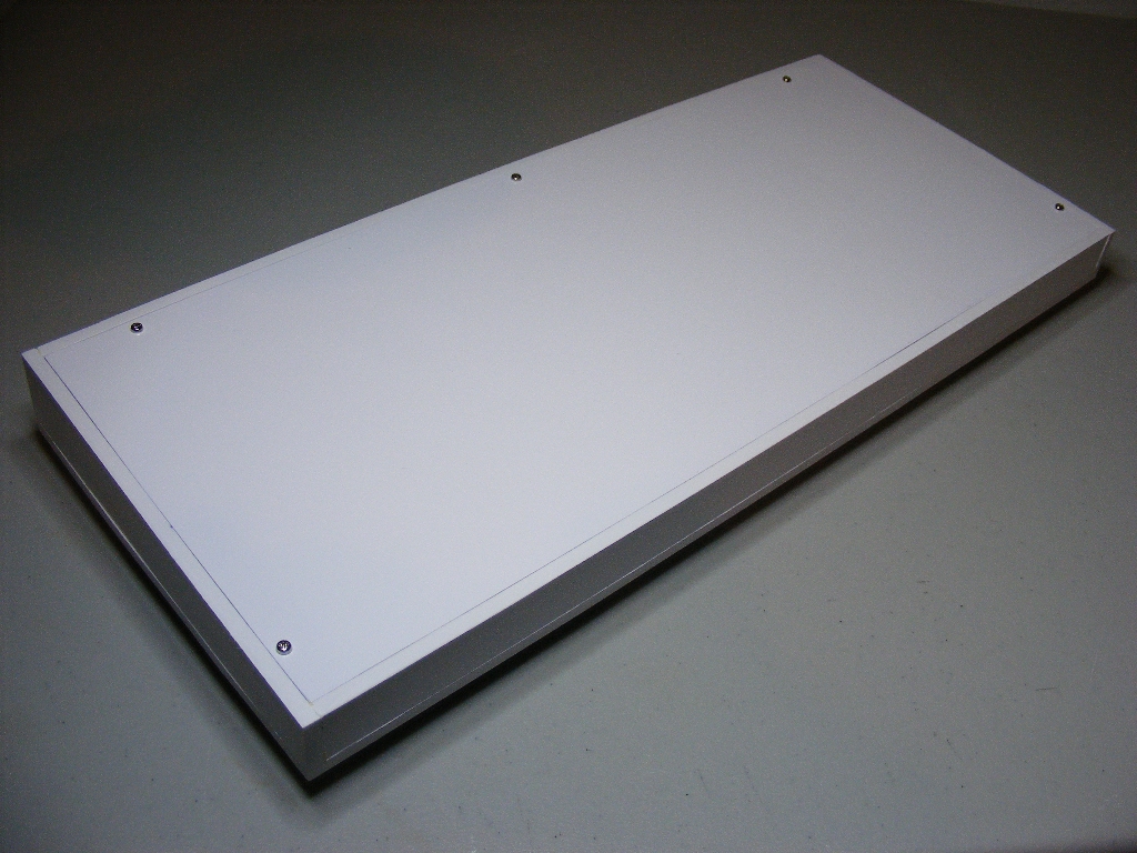
Successfully built

Keyboard - Version 1.0


Next, the description of a keyboard slightly modified from the original one. While the schematic is identical with v.0, I have decided to make a little change in the keyboard layout, by moving the "GRAPH NORM" key from the middle row to the second row on the bottom, between the "CAPS SHIFT" and "Z" keys. At the same time I enlarged the "CAPS LOCK" key, making it the same size with the "CAPS SHIFT" and "SYMBOL SHIFT" keys. This way the keyboard achieves a little more symmetry, as you can see in the drawing below which I drew as an initial plan when I started work.

It appears you don't have a PDF plugin for this browser. No problem... you can click here to download the PDF file.


Aside from these modifications, as you can also see in the drawing above, the keys are now color labeled, due to the fact that I ordered them from a specialized keyboard manufacturer.

The keycap dimensions are as follows:

PG EDT, DEL, TAB 1.25 x 1
CAPS LOCK, CAPS SHIFT, SYMBOL SHIFT1.5 x 1
SPACE 8 x 1
ENTER 0.75 x 2 x 1.5 x 1
rest of the keys 1 x 1


Keyboard schematic - v.1.0

It appears you don't have a PDF plugin for this browser. No problem... you can click here to download the PDF file.


NOTE:


The original version of the keyboard was using a 1 x 20 pin connector to the mainboard.

On the mainboard, the connector had 2 x 10 pins.

So using a 20-wire flat cable, the mainboard end of the cable could be attached to the connector in a civilized manner, whereas the keyboard end had to be spread away like a broom in order to cover a width twice as big.

That's why I designed the layout for v.1.0 using a 2 x 10 pin connector, to achieve a decent manner of connection to the mainboard through a 20-wire flat cable having 2 x 10 pin connectors at each end.


Circuit board layout - v.1.0

I designed the keyboard using MX Series switches manufactured by Cherry Electrical. The keycaps have been ordered from a specialized keyboard manufacturer.

It appears you don't have a PDF plugin for this browser. No problem... you can click here to download the PDF file.

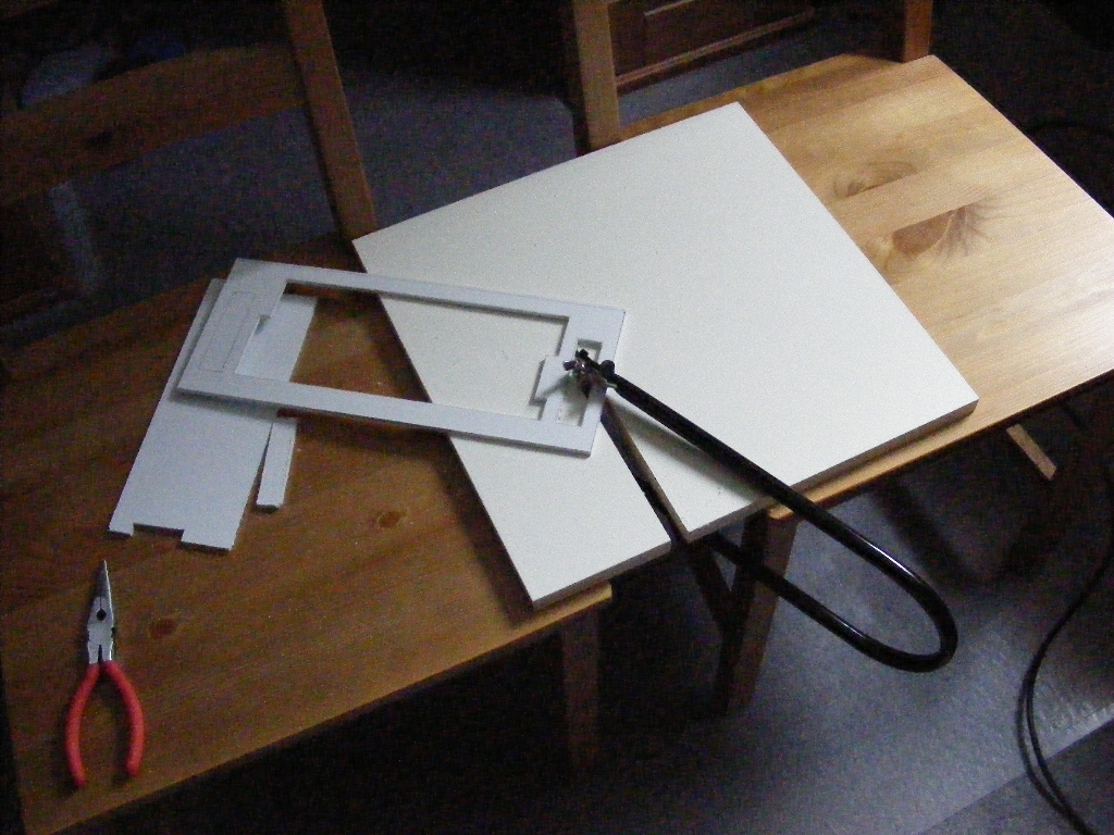
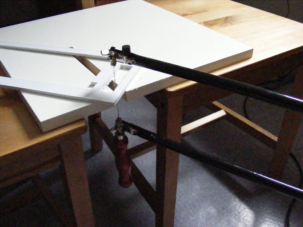
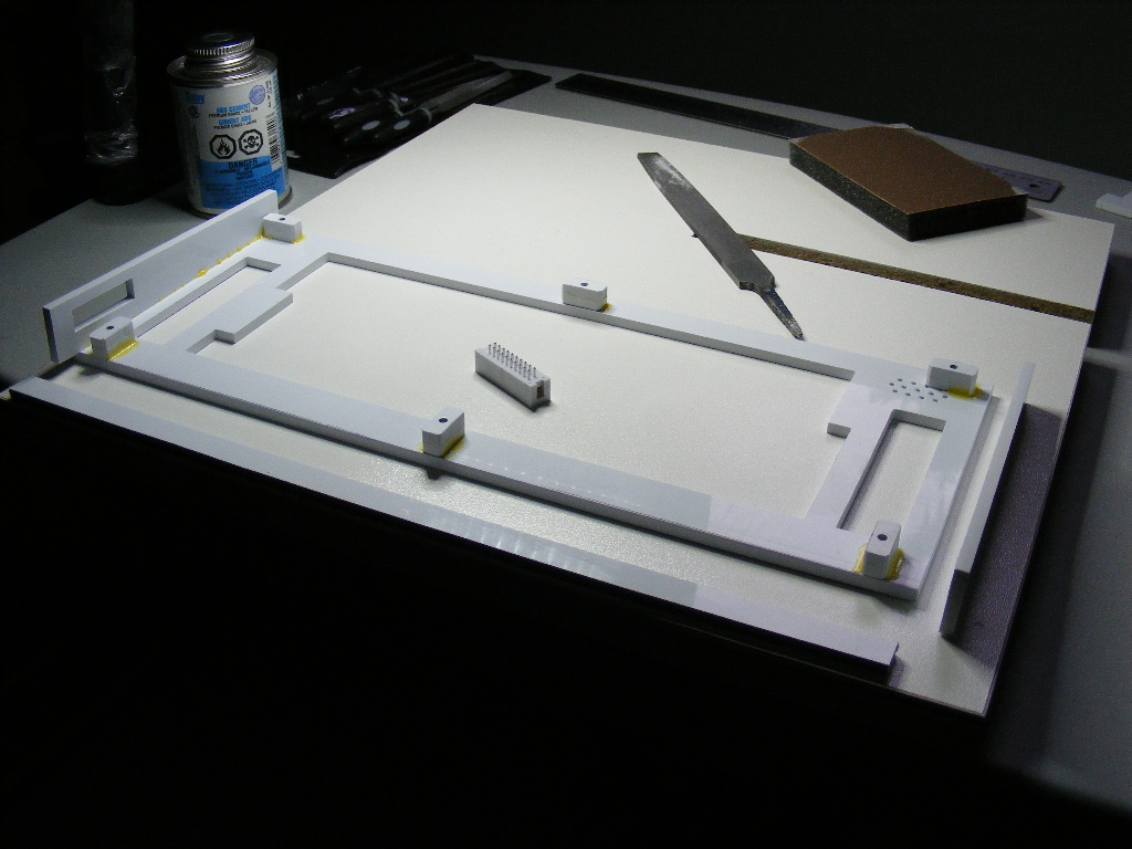
Actual construction:

When assembling it, the biggest trouble was the leveling system for the SPACE bar, consisting of a piece of thick steel wire, which I had to bend to some very exact dimensions, and of two very little pieces of thin sheet metal cut, drilled and bent to 90° which guide the thick piece of steel wire at ends (see the third image below). These two little brackets are fastened with M2 screws and nuts to the keyboard circuit board, and then secured in place with some glue.

On the back of the circuit board, I applied some Super Glue to the plastic ends of the switches protruding through the circuit board, to make sure that the switches will not get loose in time.

The speaker I used is a low power 0.015W 150 ohm mini speaker (27 mm diameter) which I attached to a corner of the circuit board using two pieces of Sticky Tac.


I maintained my 20 years old approach of building a separate case for the keyboard. As such, I had a lot of headaches building a plastic case for the keyboard. I had to come up with a manufacturing "technology", in some pretty low-tech fabrication environment. I'm showing below a few of the most relevant steps of the "process":